
A security integrator in Lagos wins a contract for 240 analogue cameras and orders “RG59 with power, 300 m reels”. The cable arrives, the cameras work, and three months later a dozen of them drop out at midday. Nothing in the order was ambiguous: the cable was RG59, it was Siamese, it was 300 m. What the order never stated was the centre conductor, and the reels had been supplied with copper-clad steel — which is perfectly correct for a video-only run and marginal for a run that also carries the camera’s DC supply. The copper number was on the invoice; the steel was inside it.
Coaxial cable is the oldest mature cable family in the catalogue, and it is the one where the description most often stops one field short of the specification. RG59, RG6 and RG11 all share a 75 Ω impedance and the same five-layer construction, so they look interchangeable on a spec sheet and behave very differently on a 300 m run. The RG number itself has not been a performance guarantee for decades: it began as a bulk radio-frequency classification in the U.S. military’s Joint Electronics Type Designation System, the /U suffix means “general utility”, and the RG unit indicator was dropped from that system altogether (MIL-STD-196E). Cable sold today under an RG label is unlikely to meet the military specification it is named after.
This guide separates what the RG label does and does not promise, compares the three 75 Ω types a CCTV or CATV buyer actually purchases, and then works through the four decisions that cause returns: conductor material, shielding, dielectric and jacket. Figures are cited at the end. Where a number is an arithmetic consequence of a cited figure, it is labelled as such — and where published sources disagree slightly, both are shown rather than averaged.

What the RG number tells you, and what it stopped telling you
The RG designation was a sequential catalogue number, not a recipe. Two cables both legitimately sold as RG6 can differ in centre-conductor material, dielectric (solid or foam), shield count and jacket compound, and still both be RG6. The label fixes one thing only — for the 75 Ω family, an impedance suitable for video — and leaves everything else to whoever wrote the datasheet.
That is why the practical definition has drifted toward dimensions. RG-6/U is generally understood to mean a 75 Ω cable with an 18 AWG centre conductor, which is 1.024 mm, and an overall diameter around 6.9 mm. RG-59 is the thinner 20 AWG member of the same family at roughly 6.1 mm, and RG-11 is the heavy 14 AWG member at roughly 10.5 mm. Those three dimensions are the ones a buyer can actually verify with a calliper at goods-in, which is a better test than reading the print legend.
One consequence worth stating plainly: because RG is a generic label, a quotation that says only “RG6” is not a specification. It is a category. The specification is the category plus conductor, shield, dielectric, jacket and the length per reel.
The five layers, and which one you are actually buying
Every coaxial cable in this family is the same five concentric elements: a centre conductor, a dielectric that holds it exactly on axis, one or more shields, and an outer jacket. The impedance — 75 Ω for video and CATV, 50 Ω for radio and antenna work — is not a property of any single layer. It is set by the ratio of the shield’s inner diameter to the conductor’s diameter, together with the dielectric constant of the insulator between them. That is why a change of dielectric material, at the same nominal size, moves the impedance, and why cheap substitutions inside a cable show up as reflections rather than as an obvious fault.

In purchasing terms, layer four is where most of the cost and most of the argument sits. A single braid gives somewhere between 60% and 95% coverage depending on how densely it is woven; a foil tape gives continuous coverage but is thin and fragile; a foil-plus-braid construction pairs the two, and a quad shield stacks four alternating layers for hostile RF environments. More shielding means less leakage in both directions — less interference entering the cable, and less of the cable’s own signal radiating out of it.
RG-59, RG-6 and RG-11 side by side
The table below is the one to keep beside a quotation. It uses indicative published figures for typical constructions; a specific datasheet will differ in the second decimal place, and the ordering of the three types never changes.
| Property | RG-59 | RG-6 | RG-11 |
|---|---|---|---|
| Impedance | 75 Ω | 75 Ω | 75 Ω |
| Centre conductor | 20 AWG solid copper | 18 AWG solid copper or CCS | 14 AWG solid copper or CCS |
| Overall diameter | ~6.1 mm | ~6.9 mm | ~10.5 mm |
| Typical shield | Single braid, ~95% | Foil + braid, dual or quad | Foil + braid, dual or quad |
| Attenuation at 100 MHz | ~3.4 dB/100 ft | ~2.0 dB/100 ft | ~1.5 dB/100 ft |
| Attenuation at 1 GHz | ~12.0 dB/100 ft | ~6.1 dB/100 ft | ~5.6 dB/100 ft |
| Upper frequency | ~1 GHz | ~3 GHz | ~3 GHz |
| Practical video run | ~150–230 m | ~230–300 m | ~300–450 m |
| Flexibility | Most flexible | Moderate | Least flexible |
| Common connectors | BNC, F-type | F-type, BNC | F-type |
| Typical use | Analogue CCTV, legacy CATV, short baseband | CATV, satellite, DOCSIS, HD-over-coax CCTV | CATV trunk, long outdoor runs |
Run lengths converted from the published figures in feet; individual constructions and the acceptable loss budget of the receiving device will move them. Treat them as a planning envelope, not a guarantee.
The attenuation numbers, and how to use them
Attenuation rises with frequency and in direct proportion to length, because of the skin effect: as frequency climbs, current concentrates in a thinner surface layer of the conductor, so the effective cross-section shrinks. The practical consequence is that a cable which is comfortable at 100 MHz can be unusable at 1 GHz over the same distance — and that comparison is the whole argument for RG6 over RG59 in anything digital.
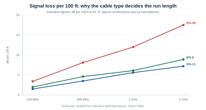
Read the chart as a budget rather than a ranking. A 12 dB loss at 1 GHz over 30 m of RG-59 means roughly 12 dB less signal at the receiver than at the source for every 30 m of that cable, before connectors and splitters take their share. Some devices tolerate that; DOCSIS modems and satellite receivers generally do not. This is also why the same RG-6 measured at 1 MHz shows about 0.2 dB per 100 ft and at 1 GHz about 6.2 dB per 100 ft on the reference curve — a thirty-fold change in loss for a thousand-fold change in frequency, which is why a single “low loss” claim on a product page tells a buyer nothing without a frequency attached to it.
Two smaller figures from the same family are worth carrying: RG-59 has a capacitance of around 20 pF/ft (60 pF/m), and RG-6’s published losses run 0.2 dB at 1 MHz, 0.6 dB at 10 MHz and 2.0 dB at 100 MHz per 100 ft. None of these decides an application on its own, but each is something a factory can quote and a buyer can measure.
Siamese coax: when the camera needs power as well as video
Most analogue CCTV installations do not run a single coax. They run a Siamese construction: one 75 Ω coaxial element for video, bonded alongside a two-conductor power pair in a shared figure-eight jacket. It halves the number of pulls, and it changes the conductor decision completely — because the power pair is carrying direct current, and the coax may be carrying the camera’s supply return as well on some designs.
This is the single most common specification gap we see in CCTV orders. Video-only coax can legitimately use a copper-clad steel centre conductor: at radio frequencies the signal travels almost entirely in the surface layer, so a thin copper skin over a steel core behaves very close to solid copper, at lower cost and with higher tensile strength. Once the same conductor has to pass DC current for a camera or an LNB, that logic inverts — solid copper conducts through the whole cross-section, and copper-clad steel does not. The correct split is therefore by application, not by price: solid copper wherever the coax carries power, copper-clad steel acceptable where it carries signal only.
A second Siamese detail: the power pair has its own gauge, and it is usually quoted separately from the coax. A camera rated at 12 V DC and drawing 500 mA over a 100 m run loses voltage in the pair itself, and the installer compensates by buying a higher-current supply or a thicker pair. If the purchase order names only the coax, the factory will choose the pair, and the installer will be the one who discovers the choice.
Foil versus braid versus quad: what shielding actually buys
Shielding is quoted as a percentage, and the percentage is misleading on its own. A single braid at 95% coverage is dense but still a woven mesh with holes; a foil tape is 100% continuous but only microns thick and easily cracked at a bend. The two fail in different ways, which is why the better constructions use both: the foil handles high-frequency interference, where even a small aperture leaks, and the braid adds low-frequency protection plus the mechanical strength to survive installation.
Quad shield — foil, braid, foil, braid — exists for environments where the cable runs near broadcast transmitters, substations or industrial drives. It costs more per metre and is slightly stiffer. For a residential or light-commercial CCTV installation, dual shield is the ordinary minimum and quad is optional; for an industrial site the reverse is true. Selling quad shield into a quiet environment is not a quality upgrade, it is a cost transfer; selling dual shield into a substation is a callback.
| Shield construction | Coverage | Best for | Watch out for |
|---|---|---|---|
| Single braid | 60–95% | Short runs, low-interference sites, RG-59 CCTV | Apertures leak at high frequency; not for 1 GHz+ digital |
| Foil + braid (dual) | Foil 100% + braid | Standard RG-6/11 CATV, satellite, HD-over-coax | Foil creases if the bend radius is abused |
| Quad (foil/braid ×2) | Foil 100% ×2 + braid ×2 | Industrial sites, near transmitters, long trunk | Stiffer, larger bend radius, higher cost |
| Solid tube / hardline | Continuous metal | Trunk and feeder runs | Cannot be bent; needs formed sweeps |
The naming trap: four phrases that hide a different product
Most coax disputes we are asked to arbitrate come down to a phrase that was accepted in good faith and meant something narrower than the buyer assumed. These four are worth striking out of a specification and replacing with the measurable version.
“RG6” alone. As above, this is a category, not a specification. It does not state conductor material, dielectric, shield count, jacket or reel length. Replacement: “RG-6/U, 18 AWG solid bare copper, foam PE dielectric, 60% aluminium braid over bonded foil, PVC jacket, 305 m reel.”
“Copper cable.” On a coaxial cable this phrase is almost always true and almost never sufficient. The braid is copper-plated aluminium on many CATV constructions, and the centre conductor may be copper-clad steel. Nothing is false; nothing is specified. Replacement: name the centre conductor material and gauge, and name the braid material and coverage.
“Low loss.” A loss figure without a frequency is not a figure. Replacement: attenuation in dB per 100 m at a stated frequency, for example at 100 MHz and at 1 GHz, both quoted, because the ratio between them is what tells a buyer whether the construction is honest.
“Outdoor”. Outdoor is a jacket property, not a cable type. A UV-stabilised PVC jacket survives sunlight but not burial; a PE jacket suits burial but is not fire-rated and should not enter a building. Replacement: state the jacket compound, whether the cable is flooded or gel-filled, and whether it is direct-burial rated.
Five failures that are decided at the drawing, not at the factory
1. CCS specified into a power-over-coax run. Consequence: cameras drop out under load, most visibly at midday when IR arrays switch on, and the fault is diagnosed as a power supply problem for weeks. Prevention: solid copper centre conductor named explicitly on the PO whenever the coax carries DC.
2. RG-59 chosen for HD-over-coax because it is thinner. Consequence: the cable fits the existing conduit, which was the point, and then fails to carry the bandwidth over the required distance. Prevention: fix the resolution and run length first, then choose the cable, then check the conduit can take it.
3. 75 Ω and 50 Ω mixed in one system. Consequence: reflections at every junction, elevated VSWR, and in transmit systems a real risk of damage to the output stage. Prevention: state the impedance on every line item, including patch leads and splitters.
4. Connector chosen to fit the cable rather than the equipment. Consequence: an F-type crimped onto RG-11 with the wrong ferrule yields an intermittent shield contact that tests fine on the bench and fails on a ladder. Prevention: name the connector series and the cable series together, and specify that the connector is rated for that cable diameter.
5. Bend radius ignored in the packing and installation plan. Consequence: RG-11 kinked behind a trunking lid looks fine and loses a few dB permanently, because the dielectric has been deformed and the geometry that set 75 Ω no longer holds. Prevention: specify a minimum bend radius, and pack coils to at least that radius.
A ten-line coaxial specification for a purchase order
The following ten lines, filled in completely, remove essentially all of the ambiguity this article has described. They are written in the order a factory needs them.
| # | Field | Example entry |
|---|---|---|
| 1 | Type and impedance | RG-6/U, 75 Ω ±3 Ω |
| 2 | Centre conductor | 18 AWG (1.024 mm) solid bare copper |
| 3 | Dielectric | Foam PE, gas-injected |
| 4 | Shield | Bonded aluminium foil + 60% aluminium braid (dual) |
| 5 | Jacket and rating | PVC, CM; or PE for direct burial |
| 6 | Attenuation to be met | ≤2.0 dB/100 ft at 100 MHz; ≤6.2 dB/100 ft at 1 GHz |
| 7 | Length and packing | 305 m per wooden spool, spool returnable |
| 8 | Connector interface | F-type male compression, rated for 6.9 mm cable |
| 9 | Marking | Print legend: type, conductor, shield, jacket rating, metre marks, factory code |
| 10 | Test and acceptance | 100% continuity and shield-integrity test; sample attenuation report per batch |
Field 6 is the one buyers most often leave blank, and it is the only field that converts a promise into an acceptance criterion. A supplier who will not write a loss figure against a frequency has not specified the cable, whatever else the quotation contains.
Inspecting a delivery in fifteen minutes
Coax is unusually easy to check, because almost everything that matters is either visible at the stripped end or measurable with a multimeter and a calliper. Four checks cover the majority of real non-conformities.
Measure the centre conductor. Strip 40 mm and measure with a calliper. 1.024 mm indicates 18 AWG and points to RG-6; 0.81 mm indicates 20 AWG and points to RG-59. A conductor that is undersized for the declared type is the clearest single sign of a substituted construction.
Check the conductor material, not just the colour. Scratch the surface of the centre conductor with a blade. Bright copper all the way through is solid copper; a silver-grey core under a copper skin is CCS. Both are legitimate products; only one is what a power-carrying run needs.
Count the shields. Peel the jacket back and count the discrete layers between dielectric and jacket. Two layers is dual shield; four is quad. Compare against the PO rather than against expectation.
Measure the reel, not the label. Weigh or measure one reel and compare against the declared length. Short reels are the oldest trick in the cable trade and the least visible until a run comes up 20 m short on the last camera.
Frequently asked questions
Can I use RG-59 instead of RG-6 for cable TV or internet? Over a short distance RG-59 will carry the signal, but it is the wrong default for digital services. At 1 GHz, RG-59 loses roughly 12 dB per 100 ft against about 6 dB for RG-6, so a run that is comfortable on RG-6 becomes marginal on RG-59 as distance or frequency rises. Most operators specify RG-6 for new installations.
Is copper-clad steel acceptable? For signal-only runs at radio frequency, yes — the skin effect means the copper layer carries nearly all the current, and CCS is cheaper and stronger. For any run that also carries DC power, use solid copper. The distinction is application, not quality.
Do I need quad shield? Not by default. Dual shield is the ordinary minimum for commercial CCTV and CATV. Specify quad where the cable runs close to transmitters, substations or variable-frequency drives, and accept the extra stiffness and cost as the price of that environment.
Why does the same cable show different loss figures from two suppliers? Because the figures are for different constructions and different temperatures. Loss rises with temperature and depends on conductor size, dielectric type (foam loses roughly 15% less than solid) and shield construction. Always compare attenuation at a named frequency, and ask for the test conditions.
Can RG-11 replace a fibre run? No. RG-11 buys distance over RG-6 by virtue of a larger conductor — roughly 40% less loss at the same frequency — but it remains a copper transmission line with frequency-dependent loss. Where the distance exceeds what copper can carry, the next step is twisted pair or fibre, not a bigger coax.
What does “flooded” mean on a coax datasheet? A water-blocking gel fills the spaces between braid and jacket so that a nick in the jacket does not allow moisture to travel along the shield. It matters for buried and outdoor runs, and it makes the cable noticeably stiffer and heavier.
Sources and how the figures were used
Conductor gauges, the 1.024 mm equivalence for 18 AWG, the RG-6 reference attenuation curve (0.2 / 0.6 / 2.0 / 6.2 dB per 100 ft at 1 / 10 / 100 / 1,000 MHz), the 75 Ω impedance and the RG designation’s military origin are taken from the Wikipedia entries for RG-6, RG-59 and Coaxial cable. The RG-59 capacitance of about 20 pF/ft (60 pF/m) and its typical use at baseband video, together with the note that its high-frequency loss forces RG-6 or RG-11 for longer runs, are from the RG-59 entry. The comparison figures at 100 MHz, 500 MHz, 1 GHz and 2 GHz, the 60–95% braid coverage range, the approximately 15% lower attenuation of foam dielectric, and the run-length envelopes are indicative values published by a cable distributor and are reproduced as indicative, not as a guarantee of any specific construction. Metre equivalents of the published foot-based run lengths, and the ratio statements between types, are arithmetic performed on those cited figures and are labelled as such in the text.