
Shielding is the line item buyers argue about most and understand least. Two quotations arrive for the same “Cat6A patch cable”, one is 30 % cheaper, and the only visible difference on the drawing is a few words: U/UTP versus S/FTP. Those words decide whether the cable holds a 10 Gbps link inside a factory full of variable-frequency drives, whether the assembly still passes radiated-emission testing when it is installed, and whether the shielding you paid for does anything at all after the connector is crimped on. This guide explains every shield construction in volume production in 2026, what each one is genuinely good at, how the naming systems disagree with each other, and how to write a specification that survives the first production run.
What a cable shield actually does
A shield is a conductive layer wrapped around a conductor or a pair. It does two jobs at once: it stops energy radiating out of the cable, and it stops external fields coupling in. Which of the two you care about depends on the product — an HDMI cable mostly has to keep its own high-speed pairs quiet, while a sensor cable in a welding cell mostly has to survive what is already in the air.
Interference arrives in four distinct ways, and they do not all respond to the same fix, which is why “more shielding” is not an answer on its own:
- Electrostatic / electric-field noise couples capacitively from a nearby voltage source. A foil shield with full coverage is the most effective countermeasure, and it only works if the shield is grounded.
- Magnetic noise from power wiring, transformers and motors couples inductively whatever the shield material. The primary fix is twisting the pair, because the induced voltages cancel; a braid helps, a thin foil helps much less.
- Common-mode noise appears when two ends of a system sit at different ground potentials. It is reduced at the receiver by a high common-mode rejection ratio, and it is the reason shielded links need a defined bonding strategy at both ends.
- Crosstalk is pair-to-pair coupling inside the same cable. Individual foil around each pair plus controlled twist lay is the standard remedy in Cat6A and above.
The four shield constructions you will be quoted
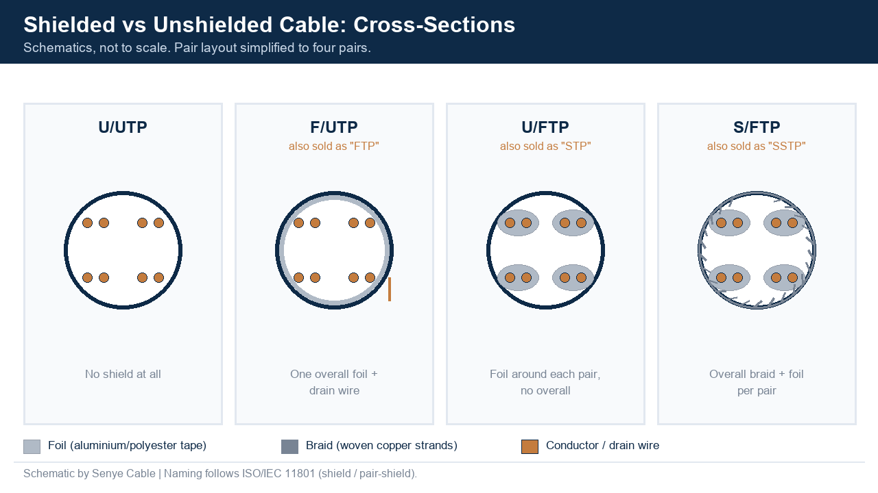
Almost every shielded cable on the market is built from four shield styles, sometimes in combination. The cross-sections below show how they differ mechanically, and the table that follows compares them on the parameters that actually appear on a quotation.
1. Foil (aluminium tape) shield
An aluminium foil laminated to a polyester carrier tape, wrapped around the cable or around a single pair. It is the only shield style that gives 100 % optical coverage with no gaps. The foil itself is thin — commonly quoted at 0.025 mm to 0.05 mm — so it cannot be clamped directly. A bare or tinned copper drain wire runs the length of the cable in contact with the conductive side and becomes the termination point.
Foil is cheap, light and thin, and it is the best available barrier against high-frequency RF. Its weakness is mechanical: repeated flexing cracks the aluminium and creates gaps, and its low-frequency magnetic performance is only fair. It is the natural choice for fixed data installations, patch cables and any assembly where cost per metre matters.
2. Braided shield
Woven strands of bare or tinned copper form a mesh around the core. Braid can never reach 100 % coverage, because the weave leaves gaps: catalogue values run from 65 % to 98 %, with commercial-grade cable typically at 70–85 % and premium constructions at 90–95 %. That is not a defect; the open mesh is what gives braid its long flex life and lets heat escape from high-power assemblies.
Braid performs best against low-frequency interference such as motor and power-line noise, and it is the only shield style that can be clamped directly into a metal backshell or an EMC cable gland for a full 360° bond. The trade-offs are real: braid adds weight, increases diameter, stiffens the cable at high coverage, and is commonly quoted at 30–50 % more cost than an equivalent foil construction. Watch the material as well — copper-clad aluminium braid is cheaper than tinned copper and behaves differently at high frequency.
3. Foil plus braid (combination shield)
An inner foil layer covers the pairs completely; an outer braid protects the fragile foil mechanically and adds low-frequency performance. Any RF that leaks through the braid gaps is stopped by the foil, and low-frequency energy the thin foil would pass is picked up by the braid. This is the construction specified for medical assemblies, robotics, EV harnesses and any program with a tight EMC margin, and it is the correct answer when a buyer cannot describe the noise environment precisely.
4. Spiral / serve shield
One or more conductors wound helically around the core, typically reaching 80–97 % coverage. Spiral is the most flexible option with an excellent flex life, which is why it survives in audio and instrumentation. It is, however, a poor choice above the audio range: the wrap acts as an inductor at higher frequencies and shielding effectiveness falls away quickly.
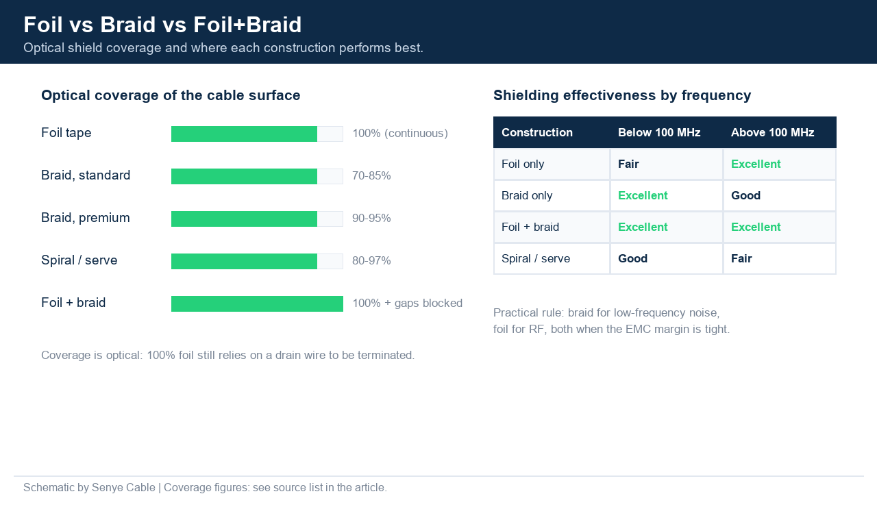
| Shield style | Coverage | Best frequency range | Flex life | Termination | Typical use |
|---|---|---|---|---|---|
| Foil | 100% | Above 100 MHz | Poor | Drain wire only | Data patch cables, fixed installation |
| Braid | 70–95% | Below 100 MHz | Excellent | 360° clamp possible | Industrial, robotics, machine cable |
| Foil + braid | 100% + gaps blocked | Full range | Good | Braid clamp, drain assisted | Medical, EV, EMC-critical assemblies |
| Spiral / serve | 80–97% | Audio only | Excellent | Clamp or solder | Microphone and instrument cable |
Table 1 — shield styles compared. “Coverage” is optical coverage of the cable surface, not a measure of performance; a 100 % foil and a 95 % braid are optimised for different frequencies.
The naming trap: why “STP” means three different cables
This is where most purchase-order mistakes begin. Older North American literature uses UTP, FTP, ScTP and STP loosely, and the same three letters have been used for an overall foil, an overall braid, and a screened twisted pair with individual pair screens. The words on a supplier’s datasheet therefore prove nothing on their own.
The international answer is the two-part designation in ISO/IEC 11801. It is written as overall-shield / pair-shield, and the letters come from German cable vocabulary — U for unshielded, F for foil, S for braid (screen). So F/UTP is an overall foil with unshielded pairs, U/FTP is unshielded overall with a foil around each pair, and S/FTP is an overall braid with foil around every pair. The standard specifies a 100 Ω link impedance for these balanced cables, which is why the designation always travels with a category number.
| What a supplier writes | ISO/IEC 11801 designation | What is actually inside | Buyer note |
|---|---|---|---|
| UTP | U/UTP | No shield anywhere | Fine for offices; fails in heavy noise |
| FTP, F/UTP | F/UTP | Overall aluminium foil + drain wire | Most common “shielded” cable |
| STP, ScTP, SFTP | Ambiguous | Anything from one overall foil to braid plus pair foils | Ask for the construction drawing |
| SSTP, PiMF | S/FTP | Overall braid + foil around each pair | Preferred wording on a PO |
| “Shielded Cat6A” | Could be F/UTP, U/FTP, S/FTP | Depends entirely on the factory | Insist on the ISO designation |
Table 2 — the naming cross-reference. Two cables that both say “shielded Cat6A” can differ in cost by a third and in EMC behaviour far more than that.
Which construction each cable family actually needs
Shielding is not a generic upgrade. Each cable family has a different reason for needing it, and the reason decides which construction is correct.
Network cable: Cat5e to Cat8
Category 6A was ratified in 2004 and became the reference cable for 10GBASE-T through IEEE 802.3an-2006, with ISO/IEC 11801 amendments adding a 500 MHz channel class from February 2008. Cat6A supports 10 Gbps across the full 100 m channel, and the 500 MHz bandwidth matters mainly because it leaves headroom to control alien crosstalk — energy coupling between neighbouring cables bundled in the same tray. That is a different problem from the pair-to-pair crosstalk inside one cable, and it is why the shielded Cat6A variants (F/UTP, U/FTP, S/FTP) exist alongside the unshielded U/UTP version. Above that, ISO/IEC 11801 Class II defines cable and connectors up to 2 GHz for Category 8.2, the only copper medium with a published standard for 25G/40GBASE-T over short channels.
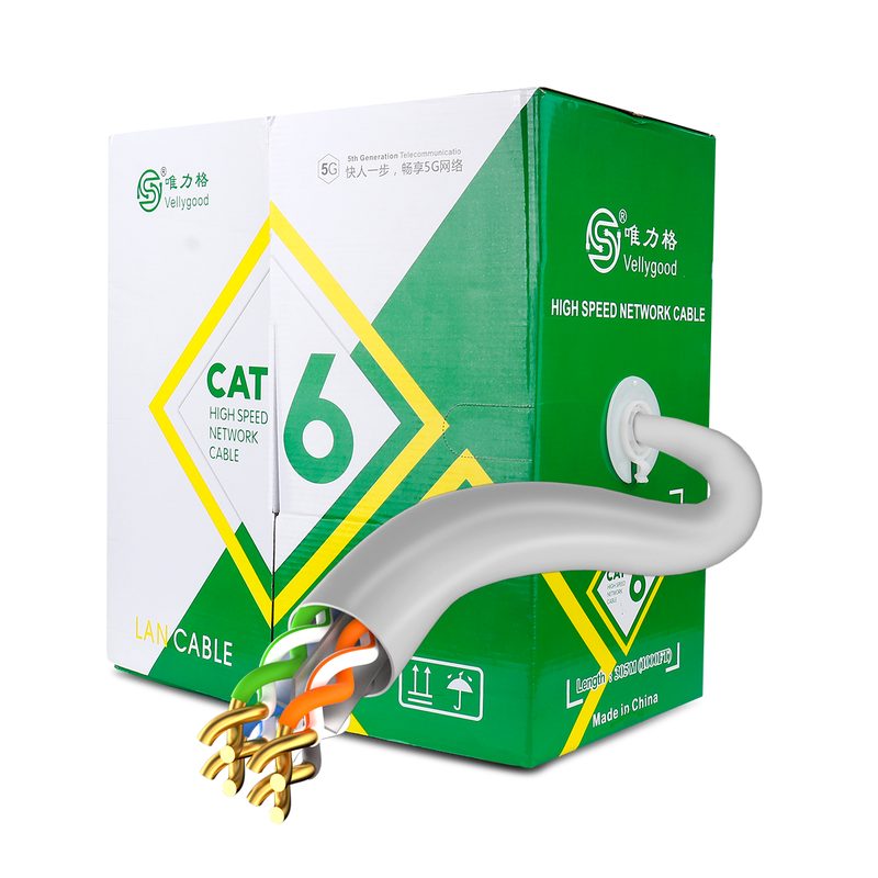
A practical rules of thumb for buyers: specify U/UTP Cat6 where the run is open office ceiling space and cost per metre dominates; step up to F/UTP Cat6A for hospitals, schools and mixed-power pathways; and go S/FTP for data centres, broadcast facilities, industrial cabinets and any installation where the customer’s EMC report already failed once. Our own network cable range covers UTP and shielded constructions from Cat5e to Cat7 in 24 AWG, 26 AWG and 28 AWG, including bulk reels and patch cords. A production example with a cross-separator is shown below.
Coaxial cable: the shield is the return path
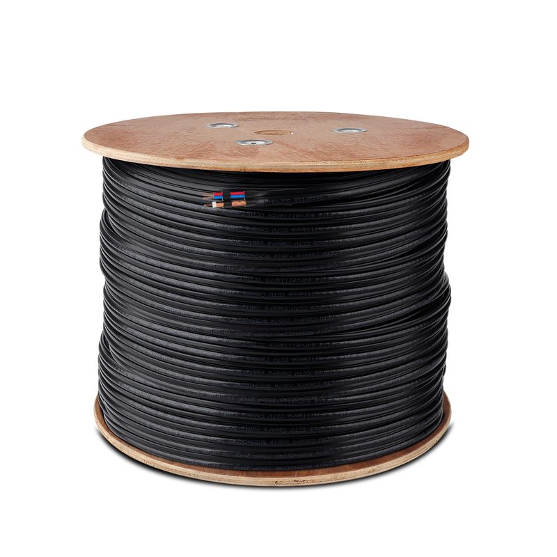
In a coaxial cable the shield is not an accessory — it is one of the two conductors. Current returns through the braid, so coverage and continuity affect signal integrity directly, not just EMC. CCTV and CATV coax is normally built with a foil plus braid combination: the foil gives the high-frequency continuity, and the braid carries the return current and survives the pull through conduit. When a CCTV installer reports intermittent video on a long run, a corroded or sparsely braided shield is a common cause, and it is invisible from the outside of the jacket.
USB and video: shielded pairs inside a shielded jacket
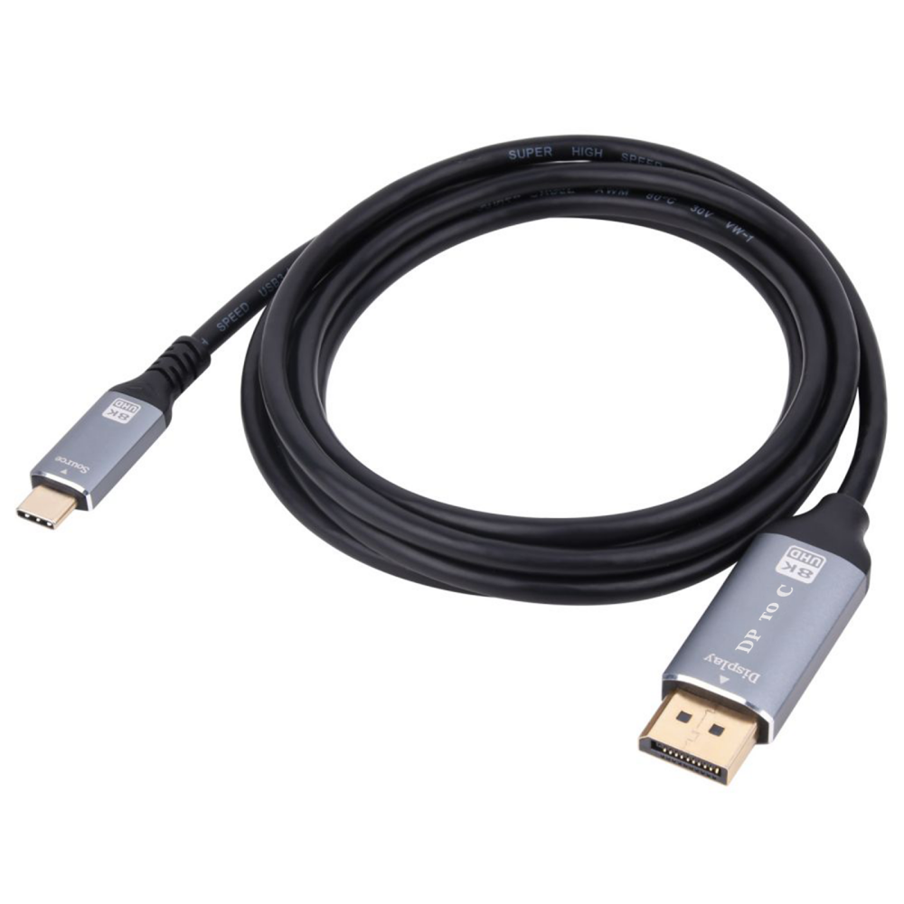
High-speed video and data assemblies are built the same way as Cat6A but with tighter geometry: the differential pairs that carry the actual signal are individually shielded to hold their characteristic impedance and to stop the pairs talking to each other, and the whole bundle gets an overall shield plus, on premium products, a braided outer layer for mechanical protection. Above a few hundred megahertz, the dominant cost driver is not the copper — it is how consistently the assembly holds 90 Ω (USB SuperSpeed) or 100 Ω (HDMI/DisplayPort differential pairs) through the connector transition. This is why a cheap cable can pass a bench test at 1 m and fail in the wall at 5 m.
A braid-shielded example from our own line is shown below; the full customisation options are listed on our DisplayPort and Type-C adapter page.
Audio: balanced, twisted and shielded for a reason
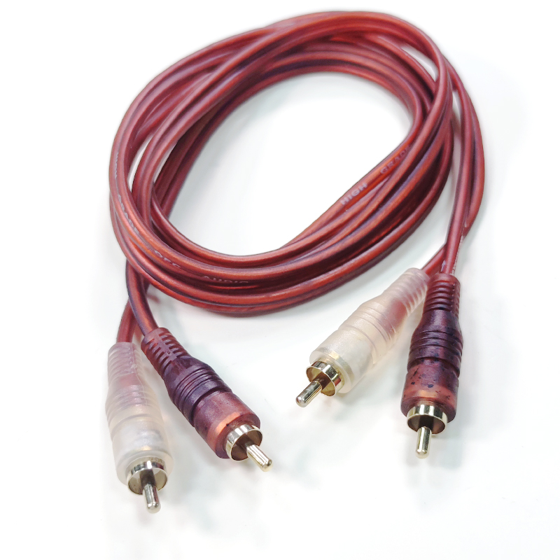
Balanced audio cable is the clearest illustration of why shielding is only part of the design. The signal travels as two equal and opposite legs, and the receiver subtracts them, so anything that couples equally into both legs is cancelled. The shield handles electric-field noise; the twist handles low-frequency magnetic noise; the receiver handles the residual common mode. Where a cable must run beside lighting dimmers or power transformers, star-quad construction — four conductors arranged so that opposite points are paralleled into each leg — typically delivers a 10 dB to 30 dB reduction in magnetically induced interference compared with a conventional two-conductor pair. The cost is capacitance: a star-quad cable behaves roughly like a standard shielded pair about 1.5 times its length, which matters on long microphone runs.
Where shielding usually fails: termination and grounding
Most EMC failures we are asked to help with are not cable failures. They are termination failures. The shield only works as a system: if the cable body is excellent but the last 30 mm behind the connector leaves the shield floating or squeezed into a thin tail, the noise finds that point immediately.
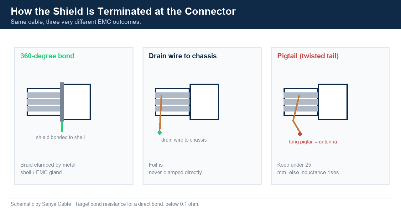
Three termination styles exist, and they are not equivalent:
- 360° bond. The braid is clamped around its full circumference by a metal backshell, a shield ferrule or an EMC cable gland at the enclosure wall. This gives the lowest inductance and is the default choice above a few megahertz. Target bond resistance for a direct shield-to-shell bond is typically documented below 0.1 Ω.
- Drain wire to chassis. The only practical option for foil constructions, since foil cannot be clamped. Perfectly acceptable for moderate data rates and control cables, provided the exposed drain length is short, the attachment point is defined in the work instruction, and strain relief does not hang off the solder joint.
- Pigtail. The shield is unbraided, twisted into a wire and put under a terminal screw. A manual pigtail presents high parasitic inductance that grows with every millimetre — a practical production limit quoted by harness engineers is under 25 mm, and above a few megahertz the pigtail starts to behave like the antenna it was meant to defeat.
The second half of the problem is bonding strategy. ISO/IEC 11801, section 10.2, states that shields should be bonded at each telecommunications outlet/connector; for permanently installed cabling the shield is normally bonded to the equipment racks, which are themselves part of the building’s earthing network. In machine and instrumentation wiring the choice is less clear-cut: some low-frequency circuits deliberately float the shield at one end to avoid a circulating loop current, while most high-frequency EMC problems only improve when the shield is bonded at both ends so noise has a low-impedance return path to the chassis. Both approaches are valid. What is never valid is leaving the decision to the installer’s habit.
| Termination method | Best suited to | Strength | Watch out for |
|---|---|---|---|
| 360° metal backshell / ferrule | Braid, foil + braid, servo and RF assemblies | Lowest inductance, stable in vibration | Higher hardware cost, tight strip-length control |
| EMC cable gland | Panel entry into cabinets and machine enclosures | Bonds the shield right at the enclosure wall | Must match cable OD and thread exactly |
| Drain wire to chassis | Foil-shielded data and control cable | Low cost, easy to assemble and inspect | Higher inductance; needs a defined length limit |
| Short pigtail | Field repairs and low-frequency bench setups only | Simple to implement anywhere | Weak above a few MHz; not repeatable |
Table 3 — termination methods. “Continuity passed” is not evidence of EMC performance; a cable can be continuous and still be an antenna.
What the compliance limits actually look like
Shielding decisions stop being theoretical the moment a product has to pass an EMC test. For multimedia equipment sold in the EU, the emission standard is EN 55032 (harmonised from CISPR 32), which replaced EN 55022. Class B applies to residential equipment and is roughly 10 dB stricter than Class A, because residential equipment sits close to radio and television receivers. The radiated-emission limits for Class B measured at a 10 m open-area or semi-anechoic site are the numbers an engineer is working against:
| Frequency band | Detector / bandwidth | Distance | Class B limit |
|---|---|---|---|
| 30–230 MHz | Quasi-peak / 120 kHz | 10 m (OATS/SAC) | 30 dBµV/m |
| 230–1000 MHz | Quasi-peak / 120 kHz | 10 m (OATS/SAC) | 37 dBµV/m |
| 1–3 GHz | Average / 1 MHz | 3 m (FSOATS) | 50 dBµV/m |
| 1–3 GHz | Peak / 1 MHz | 3 m (FSOATS) | 70 dBµV/m |
Table 4 — EN 55032 / CISPR 32 Class B radiated-emission limits (the same limits applied under EN 55022 before it was withdrawn). Cable screening and shield termination are among the few levers a buyer can still pull after the electronics are frozen.
Alongside the EMC framework, cable assemblies destined for the EU also sit inside the material-restriction rules. The RoHS Directive 2011/65/EU restricts ten substances in electrical and electronic equipment — lead, cadmium, mercury, hexavalent chromium, PBB, PBDE and four phthalates — each at a maximum concentration of 0.1 % by weight, except cadmium at 0.01 %. Where a customer also needs a REACH statement, the trigger is the same 0.1 % w/w threshold on the SVHC candidate list. These are documentation requirements, not design features, and they should be settled with the factory before tooling rather than after the container is loaded.
What shielding does not do
Three myths generate most of the unnecessary spend we see on quotations, so they are worth stating plainly. First, a shield is not a low-frequency magnetic solution. Below roughly 1 MHz the effectiveness of any shield depends mostly on the end-to-end resistance of the shield path, and a thin aluminium foil barely helps; twisting and balanced signalling are what actually cancel the induced voltage. Second, a shield does nothing if it is not terminated. A floating shield redirects interference instead of draining it, and can even make emissions worse by acting as a coupling plate. Third, shielding does not repair a bad copper decision. Copper-clad aluminium conductors, undersized AWG and cold-crimped contacts will fail a 100 m channel regardless of how much foil and braid surrounds them.
How to specify shielded cable on the order
Ten lines on a purchase order prevent nearly every shielding dispute we handle. We ask buyers for these before quoting:
- ISO designation, not marketing words — write U/UTP, F/UTP, U/FTP or S/FTP, plus the category or standard class.
- Shield material and coverage — tinned copper versus copper-clad aluminium braid, and the required optical coverage percentage.
- Drain wire yes/no — and its AWG if the answer is yes.
- Termination method at each end — 360° bond, gland, drain wire or plug termination, with the maximum exposed shield length.
- Data rate or bandwidth — the number the cable has to carry, not the version number printed on the retail box.
- Conductor specification — copper grade, solid or stranded, AWG per pair, and whether pairs are individually screened.
- Jacket material and colour — PVC, LSZH or TPE, plus the colour reference for the jacket and any colour-coding of the shield.
- Length and length tolerance — including whether reel lengths must be consistent across the shipment.
- Marking — what is printed on the jacket or overmould, and whether a certification mark must appear on the product.
- Compliance pack and market — which certificates or test reports are required, and the destination country, because labelling rules follow the market.
Five mistakes that cost buyers real money
- Accepting “shielded” as a specification. You may receive an F/UTP cable when the installation needed S/FTP, or the other way round — a cost difference of roughly a third with no written record to arbitrate.
- Paying for braid where the noise is electric-field. Above 100 MHz a 100 % foil at lower cost usually outperforms a sparse braid. Braid earns its premium on flex life and low-frequency noise, not on RF alone.
- Ignoring termination in the price. A cable quoted with a bare drain wire will be installed with a pigtail on site by someone who has ten minutes per cabinet. If the assembly needs a 360° bond, buy the backshell or gland with it.
- Mixing shield materials inside one order. Tinned copper and copper-clad aluminium braid look identical in a photo and behave differently in test. Pin the material down in writing.
- Ordering shielding to fix a link that fails for another reason. If a channel fails, the cause is as likely to be a cold crimp, a damaged pair, an over-long run or a non-compliant connector as it is the shield. Test first, then specify.
How we build shielded cables at Senye Cable
Guangzhou Senye Network Technology Co., Ltd. has manufactured cables and cable assemblies under the Senye Cable, Vellygood and Kvst brands since 2011. Our catalogue covers more than 1,000 models across network, HDMI, USB, power, coaxial, video and audio cable, shipped to 40+ countries. We produce within the CE and RoHS framework, our factory is SGS-inspected, and every piece passes a 100 % aging test before packing. OEM and ODM are routine: custom shield construction, custom conductor AWG, printed jacket, custom length and retail packaging, with an approved golden sample kept on file so the second order matches the first.
For shielded products specifically, we build U/UTP, F/UTP, U/FTP and S/FTP network cable, foil-and-braid coaxial assemblies, braid-shielded USB and video adapters, and shielded audio interconnects. If you are not sure which construction your application needs, send us the installation environment and the noise source rather than a cable name — that is usually enough for us to recommend a construction instead of a guess.
FAQ
Is S/FTP always better than F/UTP?
No. S/FTP has a wider performance envelope and a longer flex life, but it costs more, is heavier and stiffer, and needs a proper 360° or gland termination to deliver its advantage. In a low-noise installation with correct grounding, F/UTP Cat6A will pass the same 10GBASE-T channel test.
Can I use shielded cable without grounded connectors?
You can install it, but you gain very little. The shield needs a low-impedance path to ground to drain what it has collected; ungrounded, it can increase common-mode coupling rather than reduce it.
What does the “/” in F/UTP actually mean?
It is the ISO/IEC 11801 convention: the first letter describes the overall shield and the second the shield around each pair. U = unshielded, F = foil, S = braid. So F/UTP is overall foil over unshielded pairs, and S/FTP is overall braid over foiled pairs.
How much more does shielding cost?
It depends on the construction rather than the category. A braided shield is commonly quoted at 30–50 % above an equivalent foil design, and foil-plus-braid sits above both. Ask for the three constructions priced separately — the comparison usually changes the specification discussion.
Does shielding help with ESD or lightning surges?
A shield provides a controlled path for induced current, which is why shielded and bonded cable is preferred in exposure-prone installations, but it is not a substitute for surge protection devices. Treat shielding and surge protection as two separate design layers.
Conclusion
Shielding is a system decision made of three parts: the construction inside the cable, the material and coverage of the shield, and the way it is bonded at both ends. Write those three on the purchase order in ISO language, decide the termination hardware at the same time as the cable, and ask for a golden sample before the run. Buyers who do that stop paying for foil they cannot terminate, and stop discovering the problem in an EMC chamber three weeks before launch.
Sources
ISO/IEC 11801 — generic cabling classes and shield/pair-shield designation, 100 Ω balanced link impedance, Class II up to 2 GHz (Wikipedia summary of ISO/IEC 11801-1 Edition 1.0, 2017-11; retrieved 2026-10). CommScope category 6A reference — ratification in 2004, IEEE 802.3an-2006 10GBASE-T at 500 MHz, ISO/IEC 11801 amendment February 2008. Allied Wire & Cable, “The 4 Types of Signal Interference and How Proper Shielding Can Stop Them” — noise types, foil 100 % coverage, braid 65–98 %, spiral 80–97 %, frequency guidance. Custom Wire Assembly, “Braided vs Foil Shield” (updated January 2026) — braid 70–85 % commercial / 90–95 % premium, foil thickness 0.025–0.05 mm, drain wire requirement, braid cost premium 30–50 %. Cable Harness Assembly, “Cable Shield Termination Guide” (27 April 2026) — 360° versus drain versus pigtail, 25 mm pigtail guidance, bond resistance target below 0.1 Ω, one-end versus both-end bonding. Cabling Installation & Maintenance — ISO/IEC 11801 section 10.2, shields bonded at each connector. EMCCalc EN 55032 / CISPR 32 Class B radiated-emission limits (content review 29 August 2026, values traced to CISPR 32:2015+AMD1:2019) — 30 dBµV/m and 37 dBµV/m at 10 m, 50 and 70 dBµV/m above 1 GHz at 3 m; Class B approximately 10 dB stricter than Class A. European Commission RoHS Directive page and 2011/65/EU — ten restricted substances, 0.1 % by weight, cadmium 0.01 %. Wikipedia “Star quad cable” (retrieved 2026-10) citing Canare and Belden technical papers — 10 dB to 30 dB reduction in magnetically induced interference, capacitance equal to roughly 1.5× an equivalent two-conductor cable. All manufacturer figures are quoted as published and are not a substitute for testing a specific assembly.